


畅销产品


Certification : CE
Model Number : WT145
Place of Origin : China (Mainland)
is_customized : Yes
Conventional Heat Detector
4-Wire Heat Detector 12/24v Conventional Dual Heat Detector Relay Output Detector
They work perfectly with all conventional intelligent fire control panels
Advanced MCU Expert Algorithm Software.
Easy installation and maintenance
Durable sensor head, no need for replacement
SMD circuit board design-satisfactory quality and reliability guaranteed
1. GENERAL DESCRIPTION
The detectors are photo-electronic detector uses a state of-the-artoptical sensing chamber. This detector is designed to provide openarea protection and to be used with most security alarm controlpanel.
Two LEDs on each detector provide local 360° visible alarmindication. They flash every six seconds indicating that power isapplied and the detector is working properly. The LEDs latch on inalarm. LEDs will be off when a trouble condition exists indicatingthat the detector sensitivity is outside the listed limit. The alarm canbe reset only by a momentary power interruption.
The detector that initiated the alarm condition will have its red LEdand relays latched until reset by panel.Heat detector and smoke & heat detector combine a photoelectronic sensing chamber and a temperature heat detector.
2. SPECIFICATIONS
Operating Voltage Range: 9 to 28 VDC Volts Non-polarized
Standby Current: ≤200μA
Maximum Alarm Current (LED on): ≤45mA
Alarm Relay Contact Ratings: 2A@ 24V DC
Operating Humidity Range: ≤95%RH(40°C±2°C) Relative Humidity, Non-condensing
Operating Temperature Range: -10°C to 50°C (14°F to 122°F)
Smoke Alarm Sensitivity: 1.06±.26%FT
Temperature Alarm Sensitivity: 57°C (135°F) A1R (only for with heat sensor)
Height: 55 mm installed in Base
Diameter: 103 mm
WARNING
TO PREVENT DETECTOR CONTAMINATION AND
SUBSEQUENT WARRANTY CANCELLATION, THE SMOKE
DETECTOR MUST REMAIN COVERED UNTIL THE AREA IS
CLEAN AND DUST FREE.
3. INSTALLATION
NOTE: All wiring must conform to applicable local codes,
ordinances, and regulations.
INSTALL THE DETECTOR BASE
1. Open area smoke or heat detectors are intended for
mounting on a ceiling or a wall in accordance with the fire
standard in your country.
2. Attach mounting base to ceiling or wall. The base of
the detector can be mounted directly onto an electrical
junction box such as an octagonal (75mm, 90mm or
100mm), a round (75mm), or a square (100mm) box
without using any type of mechanical adapter.
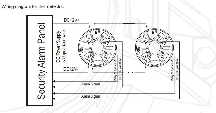
3. Position all wires flat against terminals, and fasten the
wires on the terminals, See Figure 1.
4. Terminals function description:
Terminal 1: Relay Output -COM
Terminal 2: Relay Output – NO/NC (default NO)
Terminal 3: DC Power –
Terminal 4: DC Power +
此产品暂无评论。


